Practical ATEX filling advice for your product, packs and production target

Large-container process protection

ATEX Overfill Protection for Drums & IBCs

Separate the routine fill endpoint from the abnormal protection needed if a scale, meter, controller, valve, pump or container condition fails.

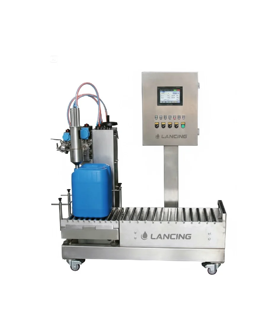
ATEX drum and IBC filling equipment used to explain overfill protection

Direct answer

Normal fill control stops at the target; overfill protection is a separate risk-control layer where the assessment requires it.

An ATEX drum or IBC filler normally uses a measured endpoint such as mass, flow or volume to stop the routine fill. Overfill protection addresses credible failures that could allow product to continue entering the container. Depending on the consequence and risk assessment, it may need an independent sensor, shut-off path, proof-test method and fail-safe response rather than relying entirely on the same controller, valve or instrument used for normal filling.

The final design depends on container capacity, product hazard, transfer pressure, pump type, valve arrangement, product in flight, foam, operator access, bunding and the ability to stop the upstream supply. A high-level switch alone is not a complete strategy unless its location, independence, response time and final isolation action are defined.

Protection layers

Separate the routine endpoint from abnormal overfill prevention.

LayerPurposeTypical evidenceImportant limitation
Normal fill measurementStops the recipe at the target mass, volume or meter quantity.Calibration, recipe, coarse/fine control, cut-off repeatability and acceptance records.Can fail through sensor, controller, valve, pump or configuration faults.
Independent high-high protectionDetects an abnormal level or quantity and initiates a separate stop where required.Independence review, proof test, response time, trip set point and final-element verification.May not be independent if it shares the same power, logic, valve or failure mode as normal control.
Physical containmentLimits the spread of a spill and protects people, equipment and the environment.Bunding or tray capacity, drainage, compatibility, inspection and recovery method.Containment does not prevent the initial loss of product or vapour release.
Operator supervisionAllows abnormal behaviour to be recognised and a stop to be initiated.Visibility, alarms, accessible stop controls, training and operating instructions.Human intervention may be too slow or unreliable as the only protective layer.

Failure review

Follow the product after the normal stop command.

  • Product already between the shut-off valve and the nozzle can continue into the pack.
  • A pump may continue to run, coast or maintain pressure after a control fault.
  • A valve can fail open, leak through or close more slowly than expected.
  • Foam may trigger a level device early or mask the true liquid level.
  • The wrong container or an incompletely empty pack can reduce available capacity.
  • A blocked return, recirculation or vent path can change pressure and fill behaviour.

Safe-state design

Define what must happen on every credible loss.

  • Loss of electrical power, control air or instrument signal.
  • Loss of earthing permissive or extraction proof.
  • Failure of the normal measurement instrument.
  • Failure of the final shut-off valve or pump command.
  • Container movement, nozzle displacement or pallet instability.
  • High-high alarm, trip, restart and manual-reset conditions.

Buyer questions

Questions to answer before calling a filler “overfill protected”.

Is a weigh scale enough to prevent overfill?

A weigh scale can provide the normal fill endpoint, but whether it is sufficient as the only protection depends on the assessed consequence and failure modes. The design should consider scale faults, incorrect tare, mechanical interference, controller failure and the product still moving after shut-off.

Should the overfill trip be independent?

Where the risk assessment requires an independent protection layer, it must not be defeated by the same failure that disables normal control. Independence can involve separate sensing, logic, power or final isolation, but the required architecture is application-specific.

How is an overfill trip tested?

Agree a proof-test method that confirms the sensor, logic, alarm, final element and reset behaviour without creating an uncontrolled release. Record the test interval, access method, bypass control and acceptance criteria.

Does overfill protection replace bunding or spill containment?

No. Prevention, detection and containment serve different purposes. The site assessment determines the appropriate combination of shutdown, drainage, bunding, trays, spill recovery, ventilation and emergency response.

FAT and SAT

Test both the endpoint and the abnormal trip.

  1. Verify container identification, tare or zero and the normal fill target.
  2. Confirm coarse/fine stages, product-in-flight compensation and valve closure.
  3. Simulate the normal measurement failure or agreed abnormal condition safely.
  4. Prove the independent trip, pump/valve isolation, alarm and latched state.
  5. Check the restart sequence cannot bypass an unresolved high-level condition.
  6. Repeat site-interface tests during SAT with the real transfer system and utilities.

Authoritative context

Independence and common-cause failures need explicit review.

An HSE safety notice on an overfilled vapour-recovery unit identified a protection system that was not independent of the basic process control system, so the same failure disabled both. The machinery design for a drum or IBC filler must apply the relevant risk assessment to its own measurement, shutdown and final elements rather than copy another process architecture.

Read the HSE safety notice on overfill protection independence.

Need a filling system that fits your product, packs and output?

Share your SDS, hazardous-area information, containers, fill volumes, target output and any capping or labelling stages.

Get my machine recommendation
Call 01494 623015Get a quote