Practical ATEX filling advice for your product, packs and production target

Integrated fill-cap-label system

Complete ATEX Filling Line

Bring container handling, filling, capping, labelling and discharge together as one coordinated line for compatible flammable products.

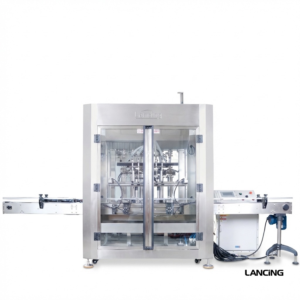
Complete ATEX explosion-protected filling capping and labelling line

Machine overview

Keep every hand-off working as one line.

A complete line may include bottle unscrambling, filling, cap feeding, capping, labelling, coding, inspection, conveying and sorting. The real engineering challenge is not only the individual machine—it is the transfer, control and safe operation of the whole process.

The line layout is developed around the site classification, container and closure range, product supply, ventilation, operator access, output and changeover requirements.

Hazardous-area suitability is project-specific.

The final machine category, marking, electrical and non-electrical equipment, controls, documentation and installation requirements must match the competent site assessment and agreed specification.

Complete ATEX explosion-protected filling capping and labelling line

Key features

Tailored to your product and production needs.

1

Protected line modules

Filling, capping and labelling modules are reviewed against the classified area and complete ignition-risk assessment.

2

Servo volume control

Compatible servo-dosing routes can allow recipe-based volume setting and repeatable changeovers.

3

Multiple closure styles

Cap feeding and capping can be configured for the actual screw, pump, trigger or specialist closure.

4

Bottle presentation

Unscramblers, infeed tables and guides stabilise containers before filling.

5

Line control

Interlocks, emergency stops, accumulation and machine status are coordinated across the line.

6

Lifecycle support

Installation, commissioning, training, spares and maintenance can be planned with the machinery.

Technical data

Key capabilities to confirm for your project.

Typical stationsBottle feed → fill → cap → label → inspect / sort
ProductsCompatible flammable liquids and pastes after product and hazardous-area assessment
FillingServo, piston, pump, flow-meter or weigh route according to application
ClosuresMultiple cap types with manual, assisted or automatic feeding
LabellingRound, front-and-back or other label route according to container
Electrical supplyProject-specific; module reference supplies may be 110/220 V
ControlsCoordinated line PLC / HMI, interlocks and emergency-stop architecture
SafetyProtected components and documentation to the agreed project category and scope
OptionsCap feeding, label inspection, coding, accumulation, extraction interfaces and line guarding

Indicative platform data only. Final performance, conformity, utilities and dimensions are confirmed against the product, container, hazardous-area classification and approved project specification.

Applications

Typical applications.

A

Alcohol products

Bottling lines for compatible alcohol-based products, perfumes and personal-care liquids.

S

Solvents and fuels

Integrated filling and closure handling for compatible solvents, kerosene and related products.

V

Viscous flammable products

Creams, coatings or pastes where both product behaviour and hazardous-area controls matter.

Typical supply scope

Support from specification to start-up.

  • Configured filler, capper and labeller modules
  • Bottle presentation, conveyors and discharge table as specified
  • Coordinated controls, guarding and interlocks
  • Operating, maintenance and conformity documentation
  • Optional FAT, installation, commissioning, training and starter spares

Quote brief

Send these details for a faster, more accurate recommendation.

  • Product and container range, with samples or drawings
  • Closure and label specifications
  • Target sustained output and efficiency assumptions
  • Hazardous-area classification across each line section
  • Available footprint, access, utilities and extraction
  • Coding, inspection, packing and future expansion requirements

Questions

Questions about complete ATEX filling lines.

Does every machine in the line need hazardous-area protection?

The answer depends on the classified zones and how vapour or product can reach each item. The complete line and facility layout must be reviewed, not only the filler.

Can existing cappers or labellers be retained?

Potentially. Existing equipment needs a technical and hazardous-area suitability review, plus an assessment of controls, transfers and line performance.

How is line output calculated?

Sustained output is based on the slowest practical stage after filling time, cap handling, label application, changeovers, operator intervention and accumulation are considered.

Your machine recommendation

Tell us what you need to fill — we’ll recommend the most suitable machine.

Send your product SDS, container details, fill range, target output and any ATEX information. You’ll receive a practical shortlist matched to your application.

☎ 01494 623015✉ sales@lancinguk.com

Direct support for new machines, line upgrades and complete filling projects.

Protected by built-in anti-spam checks. No third-party CAPTCHA or tracking service is used.

Line-level scope

Define the hazardous-area boundary and every machine interface before the line is built.

A complete filling line combines equipment that may have different process functions and different exposure to vapour or product. The filler, capper, labeller and conveyors should not be specified as isolated purchases if the classified area, controls or container transfers connect them.

InterfaceQuestions to close
Product supply to fillerSource vessel, pump, hoses or pipework, isolation, drainage, recirculation, leak response and cleaning responsibility.
Filler to capperOpen-container travel, drip control, vapour release, accumulation, rejects and the location of cap feeding and operator access.
Capper to labellerClosure verification, residual vapour, container cleaning or drying, line speed and whether labelling equipment sits inside the classified boundary.
Controls and safetyPLC/HMI ownership, emergency-stop zones, permissives, extraction or earthing interfaces, safe restart, fault recovery and remote signals.
Facility servicesPower, compressed air, ventilation, extraction, drainage, fire controls, room layout, access and installation verification.

The line layout should show the classified-area boundary, not only machine footprints.

Include release points, extraction hoods or enclosures, operator positions, doors, access routes, product supply and the equipment that may be affected by vapour migration. The drawing becomes a shared reference for the machinery supplier, site engineer and competent hazardous-area assessor.

Controls, FAT and SAT

Prove the sequence, then verify the installation.

Factory acceptance should demonstrate the agreed line sequence with representative containers, closures and product conditions. Site acceptance then confirms the services and safety interfaces that depend on the installation.

I

Interlocks

Test no-container/no-fill logic, machine-to-machine permissives, accumulation, rejects, emergency stops and the required response to extraction, guarding or earthing signals included in scope.

B

Balanced output

Measure sustained output through the complete sequence and identify the real constraint, including cap feeding, labelling, rejects, operator replenishment and changeovers.

S

Site verification

Confirm final earthing, utilities, airflow or extraction interfaces, equipment locations, access, installation checks, training and the documents handed to the operating team.

Cleaning and changeover should be tested as operating modes, not left as informal procedures. The scope should state which modules contain product, how open containers are cleared, how line sections are isolated and how a safe clean state is confirmed before maintenance or a product change.

What is the difference between line FAT and SAT?

FAT verifies the agreed machine and line functions under stated factory test conditions. SAT verifies installation-dependent matters on site, such as final utilities, extraction, earthing, line position, interfaces with existing equipment and the production conditions that could not be reproduced at the factory.

Can downstream machinery sit outside the hazardous area?

Potentially, if the competent area classification and process design place it outside the boundary and control vapour or product transfer appropriately. The decision must come from the real release sources, ventilation and layout rather than a fixed distance assumed for every project.

Should the line controls be included in the ATEX review?

Yes. Operator devices, control panels, sensors, safety functions, interlocks and any equipment outside the hazardous area that contributes to safe functioning need to be considered within the applicable equipment and machinery scope.

General packaging-line planning outside this domain’s hazardous-area focus is covered by packaginglines.co.uk. For an ATEX project, that wider line design must be reconciled with the declared zones and ignition-control strategy.

Chemical filling line controls

Write a cause-and-effect schedule for the complete ATEX line before software and interfaces are finalised.

A coordinated chemical filling line needs an agreed response to faults and unavailable services. The schedule should state what is detected, which modules stop, whether product valves close, how open containers are managed and what conditions permit a controlled restart. It becomes a common reference for machine controls, the facility and the site’s hazardous-area measures.

Event or conditionResponse to defineEvidence to agree
Extraction or ventilation permissive unavailableWhether filling is inhibited, an active fill is completed or stopped, valves isolate and an alarm requires authorised reset.Signal source, fail-safe state, delay assumptions, factory simulation and site airflow or commissioning evidence.
Earthing or bonding condition not provenWhether container entry, product flow or the complete line is inhibited and how a failed connection is cleared.Monitoring scope, connection points, proof-test method, bypass control and the real container types covered.
Capper unavailable or closure feed emptyHow filling stops before open containers accumulate, where filled packs wait and how the line is emptied safely.Accumulation capacity, open-pack exposure, reject route, operator action and restart sequence.
Container misfeed or fallen packNo-fill logic, conveyor stop zones, access control, spill response and recovery without unexpected movement.Representative fault tests, guard or access interlocks and the reset procedure.
Emergency stop or power/air lossValve and actuator state, retained pressure, uncontrolled gravity flow prevention, container release and restart checks.Cause-and-effect test, energy isolation, safe-state rationale and site-dependent verification.

Keep the open-pack path inside the line review

Filling may create the primary release point, but capping, container wiping, reject handling and accumulation can extend the practical exposure. The layout should show release sources, extraction coverage, zone boundaries and the route taken by a filled container during normal production and fault recovery.

Labelling and coding may sit outside the classified area, but that should follow from the competent assessment and agreed layout rather than a generic distance from the filler.

Use an interface register alongside the layout

For every facility or third-party connection, record the supplier, recipient, signal or service, normal state, fault state, acceptance evidence and document owner. Include product feed, extraction, fire systems, earthing, conveyors, coding, inspection and existing equipment.

Where the broader project is primarily a non-ATEX packaging-line integration, packaginglines.co.uk owns that wider intent. This site remains focused on the hazardous-area and flammable-product interfaces.

FAT proves the agreed factory-reproducible sequence; SAT closes installation-dependent evidence.

Factory tests can simulate permissives and faults, measure sustained line output and demonstrate recovery. Final extraction performance, installed earthing, room services, equipment location and interfaces with site systems normally require verification at SAT. The ATEX filling trials and FAT guide provides a structure for separating those records.

Integrated line control

Treat the fill-cap-label sequence as one controlled hazardous-area process.

The line boundary should include every stage that can affect an open, filled or rejected container. Infeed starvation, capper faults, label-station stops and discharge blockage can change where product waits and how the filler must respond.

Cause-and-effect schedule

List normal start, stop, pause, emergency stop, power loss and recovery for every module. Define signal ownership, safe states and reset conditions. The controls and interlocks guide gives a practical structure.

Installed interfaces

Coordinate area classification, extraction, earthing, power, air, product feed, drainage, access and fire controls against one layout revision. Use the site-preparation guide before delivery.

Compare total project scope before order.

The ATEX filling machine cost guide separates equipment, integration, facility works, evidence and lifecycle items so competing quotations can be compared on the same boundary.

Complete-line questions

Questions that turn separate machines into one controlled ATEX filling line.

Line performance and safe recovery depend on signals, container state and interface ownership across every module, not only the filler.

How should an ATEX filling line respond to a downstream blockage?

The line should follow an agreed cause-and-effect response that prevents uncontrolled accumulation of open, filled or unstable containers while placing product flow and movement in the defined safe state. The response may pause infeed, inhibit new fills, complete or stop the active dose and hold containers at controlled positions.

Define the detection point, maximum accumulation, state of the current pack, capping availability, alarm, operator action and restart sequence. Test the blockage at more than one point because a stop before the capper can have a different consequence from a stop after closure.

Which signals should be exchanged between the filler, capper and labeller?

Each module should exchange the minimum clear signals needed to coordinate readiness, demand, blocked or starved state, faults, emergency conditions and controlled restart. The exact interface depends on the line architecture, but vague “volt-free contact” descriptions are insufficient without signal meaning, normal state and response.

Create an interface schedule showing signal owner, electrical or network method, timing, safe state, alarm text and FAT/SAT test. Retained third-party equipment should be included rather than treated as a black box.

How should containers be tracked through a hazardous-area filling line?

Container tracking should preserve the status of each pack from detection through filling, closure, inspection and discharge so that partial, rejected or unverified containers cannot be mistaken for accepted product. Tracking may use positions, sensors, recipe state and reject confirmation rather than a complex serialised system.

Specify what happens after a stop, manual removal, sensor fault, power loss or reintroduction of a container. The recovery method should be understandable to operators and testable without bypassing protective functions.

What belongs in the cause-and-effect matrix for a complete ATEX line?

The cause-and-effect matrix should cover every condition that changes whether the line may start, continue, stop, isolate or restart. Typical inputs for review include container position, guards, emergency stops, product supply, extraction, earthing or bonding, full or empty sensors, downstream availability, rejects, utilities and communication faults.

For each input, record the affected machines, product-valve state, motion response, alarm, reset authority and proof method. The controls and interlocks guide provides a wider framework.

Review retained equipment before accepting an upgrade boundary.

The existing-line upgrade guide explains why cappers, labellers and conveyors must be assessed as part of the operating case. Use the output guide to set a line-level acceptance test.

Open-pack control

Treat filling, transfer and closure as one controlled process until the pack is secure.

The hazardous and production case does not necessarily end when the nozzle closes. Product can remain on the neck, in the nozzle tip or in an open container while it moves to the capper. Downstream stops can also create an accumulation of filled but unsecured packs.

What should the line do if the capper cannot accept a container?

The line should move to the documented safe state without continuing to create open filled packs that have nowhere controlled to go. The cause-and-effect schedule should define whether new fills are inhibited, which conveyors stop, how required extraction remains available and how the operator recovers the affected containers.

Plan the fill-to-close sequence

Use a line layout, interface register, equipment schedule, control narrative, cause-and-effect table and FAT/SAT traceability matrix. These records show which equipment owns each sensor, permissive, reject, stop and recovery action.

Review the evidence and handover guide

Line conditionQuestion to resolve before controls are finalised
No cap availableDoes the container wait before filling, stop after filling or move to a controlled reject, and what prevents further open-pack accumulation?
Wet neck or drip detectedHow is the pack contained, cleaned or rejected without transferring product onto the conveyor and capping equipment?
Extraction permissive lostWhich machine functions are inhibited, what remains energised for a safe state and how is restart authorised?
Downstream blockageWhere can containers accumulate, how many may remain open and which upstream stages must stop?
Emergency stopHow are product valves, pumps, nozzle movement, conveyors and external utilities brought to the defined safe condition?

Make every interface testable.

Provide representative product, containers and closures where possible, then identify which tests belong at FAT and which depend on the final site. The trial and FAT guide explains how to keep assumptions, deviations and SAT actions traceable.

Additional line interfaces

Include large-pack handling and inerting in the same cause-and-effect review.

Need a filling system that fits your product, packs and output?

Share your SDS, hazardous-area information, containers, fill volumes, target output and any capping or labelling stages.

Get my machine recommendation
Call 01494 623015Get a quote