Automatic
Automatic ATEX filling
Multi-head filling for conveyor-fed bottles and compatible flammable liquids.
View solution
Chemical and solvent packaging
Choose filling machinery for flammable solvents, industrial chemicals, cleaners and reagents around your SDS, compatibility, vapour, static and container requirements.
Application factors
Flash point, vapour release and area classification affect equipment, ventilation and operating controls.
Concentration, temperature and cleaning method determine wetted parts, seals, hoses and nozzles.
Diving nozzles, fill profiles and cut-off can improve filling of volatile or foaming liquids.
Container material, product transfer and line components influence grounding and bonding design.
Small bottles, jerrycans, pails and drums need different handling, weighing and closure stages.
Capping, labelling, induction sealing and conveying must be reviewed with the classified area.
Machinery shortlist
Multi-head filling for conveyor-fed bottles and compatible flammable liquids.
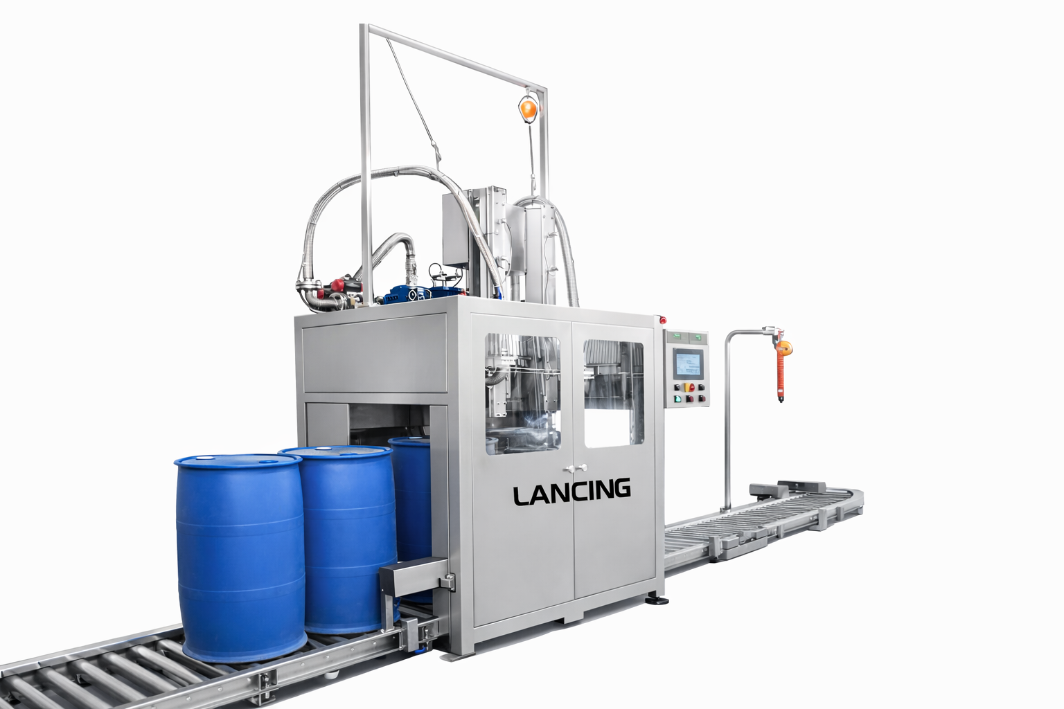
View solutionMass-based filling for common 10–30 litre chemical packs.
View solutionPP, PTFE, PVC and product-specific contact routes for aggressive liquids.
View solutionQuote checklist
FAQs
Only after both hazard and compatibility reviews. A shared platform may be possible, but seals, hoses, product contact parts, cleaning, vapour and changeover controls must all suit every product.
They can help with splash, foam and vapour release for suitable containers, but nozzle material, travel and fill profile must be selected for the actual product.
Yes. Closure feeding, cap placement and torque control can be considered, with container stability and hazardous-area requirements included in the layout.
Your machine recommendation
Send your product SDS, container details, fill range, target output and any ATEX information. You’ll receive a practical shortlist matched to your application.
☎ 01494 623015✉ sales@lancinguk.comDirect support for new machines, line upgrades and complete filling projects.
Process evidence
Chemicals and solvents may combine flammability, toxicity, corrosion, vapour, foam and cleaning constraints. The machinery specification should identify which hazard drives each design decision instead of treating every chemical as the same application.
Record the fill temperature, flash point, volatility and the credible release points at the supply connection, nozzle, open container and cleaning stage. The competent DSEAR assessment should define hazardous-area boundaries and the controls used to prevent or limit an explosive atmosphere.
Earthing and bonding depend on the product, container and transfer system. Conductive drums, metal pipework, flexible hoses and plastic jerrycans require different consideration. The machine scope should state any monitoring, permissive or connection included rather than relying on an unverified operator action.
Provide concentration and operating temperature for the product and cleaning media. Review tanks, pumps, meters, hoses, seals, valves and nozzles as one wetted path. A material approved for the product may still be unsuitable for the cleaning chemical or an intermediate mixture.
Define closed transfer where required, drain and recovery points, drip containment and how the safe clean state is verified. Open flushing can change the release scenario and should be included in the operating assessment.
| Trial input | Reason |
|---|---|
| Real formulation and SDS | Confirms hazard, compatibility and the operating conditions being tested. |
| All containers and closures | Checks neck access, stability, conductivity, cap handling and changeover. |
| Target quantities and sustained output | Allows the fill profile, cut-off and line balance to be assessed at the intended duty. |
| Cleaning sequence | Shows drainage, retained product, flush volume, waste route and operator access. |
Potentially, but both intended products and the cleaning/changeover mode must be included in the specification. Compatibility, recipe control, residual product, zone conditions and safe operating procedures need to be defined for each mode.
It may be a machine interface, a supplied hood or enclosure, a facility system or a combined scope. The quotation should name the designer, performance criteria, commissioning method and any interlock between airflow and machine operation.
It can prove agreed filling, handling, alarms, interlocks, cleaning observations and performance under the declared test conditions. It does not replace the site DSEAR assessment, final area classification or installation verification.
If the application does not require hazardous-area protection, the broader chemical-machinery intent belongs on chemicalfillers.co.uk. For this site, the focus remains the point where chemical handling and ATEX requirements meet.
Solvent filling machine specification
The product name or flash point alone does not specify a solvent filling machine. The engineering brief should connect the formulation, operating temperature, transfer arrangement, nozzle behaviour, container material, closure sequence and facility controls. A competent DSEAR assessment and area classification remain separate site responsibilities.
| Part of the process | Questions for the project brief | Evidence or sample |
|---|---|---|
| Storage and product feed | Is the source fixed or mobile? How are pressure, batch level, isolation, recirculation, drainage and hose connection controlled? | Supply layout, pump data, hose and seal materials, normal temperature and cleaning sequence. |
| Wetted path | Which materials contact the full formulation and cleaning media, including seals, valve seats, hoses, instruments and nozzle tips? | Current SDS, formulation or compatibility data, concentration, contact time and proposed material schedule. |
| Filling release | Does the product splash, foam, mist or continue to drip? How does the nozzle enter and leave the container? | Representative product and packs, intended fill profile, photographs or video of current behaviour and acceptance observations. |
| Vapour and extraction | Where can vapour be released during filling, waiting, capping, rejects, draining and cleaning? Who designs and proves the extraction? | Area-classification and ventilation drawings, design basis, interface signals and commissioning responsibility. |
| Static-control path | Which items are conductive, dissipative or insulating, and how does product move between them? | Container material, transfer arrangement, earthing/bonding strategy and any monitoring or interlock requirement. |
| Closure and downstream transfer | How long is the pack open, what closure is applied and what happens when the capper or conveyor is unavailable? | Container and closure samples, line layout, accumulation limits, reject route and fault-recovery sequence. |
A stainless-steel frame does not confirm compatibility. List every wetted component and the basis used to select it. If supplier data or experience is incomplete, identify the need for compatibility testing or a controlled sample trial rather than describing a material as universally suitable.
Corrosion resistance and explosion protection answer different questions. The corrosion-resistant filling page covers product-contact choices; this application page keeps those choices connected to the hazardous-area brief.
Drain-down, flushing, dismantling and waste recovery may expose more product or introduce another flammable cleaning medium. Define whether extraction, earthing, isolation and monitoring remain active during cleaning and how maintenance is prevented until a safe state is confirmed.
Use the earthing, bonding and static-control guide for the transfer path, and the trial and FAT guide to agree representative samples and recorded acceptance evidence.
Terms such as “vapour-proof” or “fully contained” should not be used without a defined enclosure, airflow or pressure basis, release scenario, verification method and maintenance requirement. Where that evidence is unavailable, specify the required interface and leave final performance for competent design and commissioning.
Solvent process controls
The open-container period, product supply, drips, rejects, cap placement and cleaning can each create a different release condition. The machinery and facility teams should use the same operating-case description and area-classification assumptions.
Map release sources, open-pack travel, capture or containment, monitoring and the machine response to lost extraction. See the vapour extraction guide.
Define conductive paths, container material, hoses, clamps, verification and permissives through the earthing and bonding guide.
Include draining, volatile cleaning media, opening the product path, waste handling and safe restart in the cleaning guide.
Where bottles are the principal pack, the new ATEX bottle filling page covers handling, nozzle access and closure integration.
Solvent filling questions
The product name is not enough. The machinery and site review needs the properties, process conditions and cleaning sequence that can change release, compatibility and filling behaviour.
The machinery supplier needs the current SDS sections that describe identity, hazards, composition where relevant, physical properties, handling, storage, exposure controls and incompatibilities, together with formulation and process information not normally contained in the SDS. Useful project data also includes operating temperature, viscosity, density, conductivity where known, solids, foam, product supply and cleaning fluids.
The SDS informs the review but does not define the workplace zone, extraction performance or final machine suitability. Those decisions require the actual process and competent site assessment.
These properties help describe how readily vapour may be generated and whether the real operating temperature changes the release scenario. They should be considered with fill rate, turbulence, exposed surface, ventilation, container opening, transfer pressure and abnormal conditions rather than used as a single pass-or-fail number.
Provide the normal and credible maximum product temperature and any heating, recirculation or pressure changes upstream. The competent hazardous-area assessment determines how the combined evidence affects classification and controls.
The production liquid is most valuable when viscosity, density, wetting, foam, evaporation, seal compatibility, drip behaviour or cleaning cannot be represented reliably by a safer substitute. The test plan must still address safe quantity, transport, handling, ventilation, disposal and the facility’s permission to run the material.
When a substitute is used, document what it represents and what remains untested. A successful water run, for example, should not be presented as evidence of solvent compatibility or vapour control.
Residual solvent should be included in the operating case for isolation, drain-down, recovery, flushing, disconnection, waste handling and return to service. Product trapped in hoses, valves, pumps or nozzles can create exposure, release and compatibility issues after normal filling has stopped.
Define where liquid drains, whether air or another medium is introduced, how vapour is controlled, which connections are opened and how cleanliness is verified. Cleaning fluids may create a different hazardous or materials-compatibility case from the production product.
Use the ATEX requirement guide, the flammable-liquid nozzle guide and the existing vapour extraction and containment guide to structure the review.
Chemical enquiry evidence
The SDS establishes the product-hazard starting point, but a solvent filling-machine recommendation also needs the actual temperature, transfer method, container opening, filling profile, cleaning route, ventilation and competent area-classification information.
| Evidence set | Why it changes the machine or line | What to send |
|---|---|---|
| Product behaviour | Volatility, viscosity, density, foam, wetting and stringing affect dosing, nozzle travel, cut-off and vapour release. | Current SDS, formulation/concentration, temperature range and representative sample. |
| Compatibility | The product and cleaning fluids contact several materials and dynamic seals across the complete path. | Known compatible/incompatible materials, cleaning chemistry and supplier evidence. |
| Pack and closure | Neck geometry, container conductivity, stability and closure method affect fill access, static and open-pack time. | Drawings, production samples, tolerances, cap or pump and acceptance method. |
| Site and hazardous area | Zone, ventilation, extraction, earthing, utilities and surrounding equipment define the installation interfaces. | Classification drawing, layout, extraction data, site earth/control philosophy and known gaps. |
| Acceptance | A trial or FAT is only meaningful when its product, packs, run length and pass/fail criteria are agreed. | Output basis, quality criteria, fault cases and evidence required for FAT and SAT. |
Use the identification, hazard, composition where available, handling, physical properties, stability, incompatibility, exposure-control and emergency information. Then add the process details the document cannot know.
Approve every tank, hose, seal, valve, meter and nozzle component against the exact product and cleaning duty. A generic compatibility chart or short trial is a starting point rather than long-term approval.
Include capping when open-pack transfer, cap feeding, neck wetting, downstream stops or closure inspection affect releases or sustained output. Review the fill-to-close route as one process.
Additional solvent-process decisions
Review density, temperature, air entrainment, meter compatibility, tare and the acceptance test.
Understand when oxygen control may be considered and why ventilation, Zone classification and ignition control remain necessary.
Specific solvent decisions
Use the current SDS, exact blend, containers, vapour controls, materials and closure method.
Connect suction, pressure, pulsation, compatibility and fault response to fill quality.
Choose the fill profile from foam, splash, vapour, nozzle access and cleaning evidence.
Specialist formulations
The solvent carrier is only one part of the filling brief. Pigments can change the conditioning and cleaning task; resin components can change segregation and reaction risk; volatile loss can change how a quantity check is interpreted. Keep these properties attached to the exact formulation rather than assuming that all products using the same solvent need identical machinery.
Review pigment behaviour, colour carryover and the difference between batch formulation and packaging.
Read the ink application reviewReview separate component paths, kit quantities and closure identity before choosing the filler.
Read the component-packing reviewDefine net quantity, tare, density, timing and the evidence needed to accept the filled pack.
Read the accuracy guideShare your SDS, hazardous-area information, containers, fill volumes, target output and any capping or labelling stages.