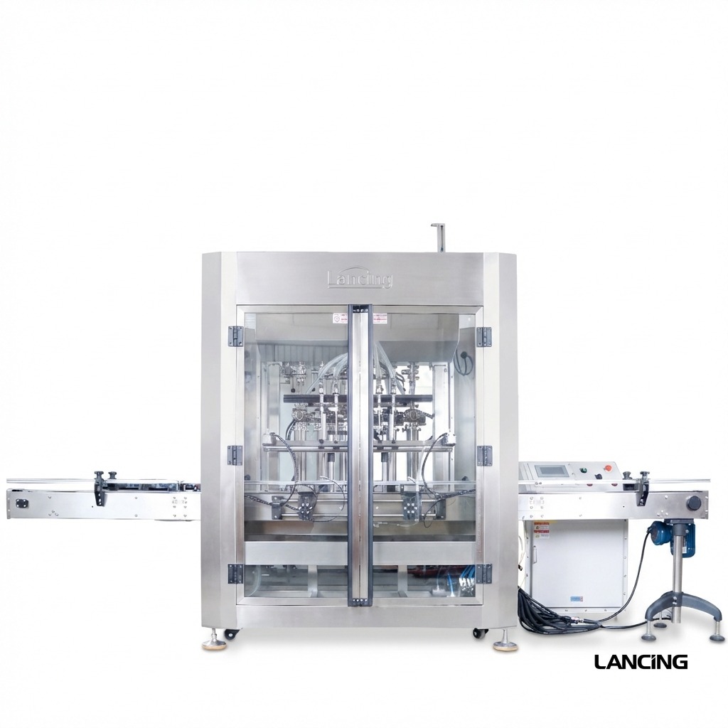
Automatic hazardous-area filler
Automatic ATEX Filling Machine
Increase throughput with a conveyor-fed filling platform configured around your flammable liquid, container format, required output and declared hazardous area.

Machine overview
What this automatic configuration can do for your line.
This platform can be configured with pneumatic actuation, protected controls, grounding and bonding provisions, diving nozzles and a dosing module selected around the product. Typical routes include piston, gear-pump, mass-flow or magnetic-flow dosing where technically suitable.
The machine is planned with the surrounding line. Bottle infeed, product supply, extraction, capping, labelling and operator access can all affect the final hazardous-area design.
Hazardous-area suitability is project-specific.
The final machine category, marking, electrical and non-electrical equipment, controls, documentation and installation requirements must match the competent site assessment and agreed specification.

Key features
Tailored to your product and production needs.
Explosion-protected design
Enclosures, cabling, operator devices and non-electrical ignition risks are reviewed against the required classification.
Pneumatic actuation
Air-driven cylinders can reduce electrical equipment at the point of fill, subject to the complete design assessment.
Grounding and bonding
Static-control provisions can be incorporated for compatible containers, product transfer and line components.
Diving nozzles
Bottom-up filling can help control splash, foam and vapour release for suitable products and containers.
Modular dosing
Piston, pump or flow-meter routes can be compared against viscosity, compatibility and required tolerance.
Line integration
Capping, labelling, conveying and bottle handling can be engineered into a coordinated cell or line.
Technical data
Key capabilities to confirm for your project.
| Reference dose range | 50 ml to 5000 ml, pump and configuration dependent |
|---|---|
| Filling heads | 1–6 heads, selected around output and fill time |
| Actuation | Primarily pneumatic with project-specific interlocks |
| Controls | Protected panel, emergency-stop and operator devices to agreed specification |
| Static management | Grounding, bonding and dissipative components where required |
| Frame and contact materials | Stainless-steel frame with sealed / compatible product-contact components |
| Air supply | Approximately 0.4–0.6 MPa reference |
| Electrical supply | 110/220 V, 50–60 Hz reference; final supply project-specific |
| Options | Weigh cells, mass flow, magnetic flow, nitrogen blanketing, extraction interfaces and guarding |
Indicative platform data only. Final performance, conformity, utilities and dimensions are confirmed against the product, container, hazardous-area classification and approved project specification.
Applications
Typical applications.
Solvents and chemicals
Acetone, ethanol blends, thinners and compatible reagents after SDS and material review.
Alcohol personal care
Perfume bases, body-mist products and alcohol-rich formulations in suitable packs.
Speciality liquids
Laboratory and industrial products requiring controlled filling in a classified area.
Typical supply scope
Support from specification to start-up.
- Machine frame and conveyor arrangement
- Configured dosing module and filling nozzles
- Protected controls, pneumatic actuators and safety interlocks
- Operation, maintenance and agreed conformity documentation
- Optional line integration, commissioning and training
Quote brief
Send these details for a faster, more accurate recommendation.
- Product SDS and full formulation / concentration information
- Zone, gas group and temperature class or site assessment status
- Fill volumes, container dimensions and neck opening
- Required sustained output and changeover pattern
- Available air, power, extraction and product-feed arrangements
- Capping, labelling, coding and conveyor requirements
Questions
Questions about automatic ATEX filling.
Can the automatic ATEX filler handle different products?
Potentially, but every product must be checked for flammability, compatibility, viscosity, cleaning, seals, hoses and the agreed hazardous-area classification. Changeover procedures also need to be defined.
Can the head count be increased?
The platform can be configured with different head counts, but output is governed by fill volume, product flow, nozzle behaviour, container indexing and downstream line capacity.
Does the machine include extraction?
Extraction and ventilation are site- and process-dependent. Interfaces or containment can be included in the project scope, but the facility design and DSEAR controls remain part of the wider site assessment.
Your machine recommendation
Tell us what you need to fill — we’ll recommend the most suitable machine.
Send your product SDS, container details, fill range, target output and any ATEX information. You’ll receive a practical shortlist matched to your application.
☎ 01494 623015✉ sales@lancinguk.comDirect support for new machines, line upgrades and complete filling projects.
Engineering brief
Define the dosing, product supply and hazardous-area interfaces as one system.
An automatic filler can only sustain output when the product reaches each nozzle consistently, containers are presented reliably and the downstream line accepts every filled pack. The selection therefore starts with more than the nominal dose range and number of heads.
Product and dosing route
Record viscosity and density at the real operating temperature, together with foam, vapour, particles, shear sensitivity and the required cleaning method. Piston, pump and flow-meter routes respond differently to those variables. The product supply tank, transfer pump, hose length, head pressure and recirculation arrangement can be as important as the filler itself.
For several products, list each formulation and concentration. Compatibility should cover seals, hoses, valves, nozzles and any wetted instrument—not only the main tank or frame material. The proposed recipe and changeover procedure should state what is drained, flushed, dismantled or replaced.
Release and ignition controls
The competent site assessment should identify where vapour or mist can be released and which parts of the line sit inside the classified area. The machinery review then considers protected electrical equipment, non-electrical ignition risks, hot surfaces, friction, impact, static, earthing and bonding, operator devices and maintenance access.
Extraction may be a facility service, a hood or enclosure interface, or part of a combined scope. The quotation should identify who designs the airflow, who proves its performance, what interlock is required and what the machine must do if extraction is unavailable.
Output should be stated as a sustained operating case.
Specify the product, fill quantity, container, number of heads, indexing pattern, fill profile and downstream stages. A short dry-cycle rate is not the same as sustained filled-container output with real cut-off, cap handling, rejects and operator interventions.
Changeover and acceptance
Plan cleaning, change parts and FAT evidence before manufacture.
Cleaning method
Define drain points, flush media, dismantling, retained product, waste handling and how the cleaned state is checked. Flammable cleaning media may create a separate operating case that belongs in the risk review.
Format change
List bottle dimensions, neck openings, closure families and label formats. Agree which rails, guides, nozzles, timing screws or recipes change and how the correct set-up is verified.
Factory acceptance
Agree the test product or representative medium, sample quantity, run length, output basis, fill-measurement method, alarm and interlock tests, reject conditions and the records supplied after FAT.
Site acceptance should separately verify installation interfaces, utilities, earthing, extraction, guarding, line controls and the operating conditions that cannot be reproduced at the factory. See the sample-trial and FAT guide for a practical evidence list.
What samples are needed for an automatic filling trial?
Provide the real product where transport and safety arrangements permit, together with every relevant container and closure, current SDS information and the intended operating temperature. The sample quantity should support start-up, adjustment, a representative run and cleaning checks rather than a single demonstration fill.
Can an existing capper or labeller be connected to the ATEX filler?
Potentially. Its location, ignition risks, controls, line height, transfer, performance and documentation must be reviewed against the classified area and the complete-line risk and conformity plan. Existing equipment should not be assumed suitable solely because it operates downstream of the nozzle.
What should be recorded during FAT?
Record the declared product or test medium, containers, recipe, target quantities, measurement method, achieved results, test duration, output basis, alarms, interlocks, rejects, changeover observations and any open actions. The record should make clear which site-dependent checks remain for SAT.
Where no hazardous-area requirement applies, broader automatic liquid-filler technology is covered by liquidfillers.co.uk and volumetric selection by volumetricfillers.co.uk.